DID YOU KNOW…
To some people, learning a new skill can be daunting, but it doesn’t have to be that way. Handplane Central has information for beginner woodworkers on the many different types of planes and what they’re used for. Why are some planes longer than others, and why do the blades all have different angles? What hand plane is best for your needs and what are the essential planes you simply can’t work without?
Handplane Central also has information on how to set up your plane properly so that it works the best way possible. Want to know the correct way to use a plane, such as for shooting the end of a board or thicknessing down to a line, then Handplane Central can help with that as well. We also have information on blade sharpening, flattening a sole or repairing a handle.
Planemaking – Casting An Adjustable Block Plane
NOTE: Click on image to enlarge.
A Block Plane And Plane With Lever Adjustment.
By A Foreman Pattern Maker.
A word in season – Shell of Block Plane – Patterns – Metal and Wooden Boss – Screw – Qualities of Shop Planes – Pin as Fulcrum for Lever – Lever Fittings – Cutting Iron – Merits of Wooden and Iron Planes – Metal Plate on sole of Wooden Plane.
I have noticed once or twice in “Shop” expressions very nearly amounting to strictures with reference to instructions given on the methods to be followed in making certain tools at home, when the tools that are described may be purchased of most hardware merchants and dealers in tools. Others again show as much desire as others evince disinclination for papers such as I am now about to write, and declare that the information that they derive from them is alike useful and welcome. Doubtless there is much to be said on both sides, inasmuch as some have neither time nor inclination to do anything of the kind for themselves, and others are better pleased to use anything that has cost them both time and trouble to make better than the best of its kind that can be purchased at the tool shops. I think myself, however, that the time spent in reading the article is by no means lost, nor the space that is taken up by it in the magazine to be regarded as wasted, for due comprehension of the construction of a tool invariably leads up to better ability to use it. It is far from likely that every reader can find equal satisfaction or benefit from the perusal of every paper, but it is possible to rest contented even with that which may not be immediately profitable to himself when he remembers their importance and utility to others.
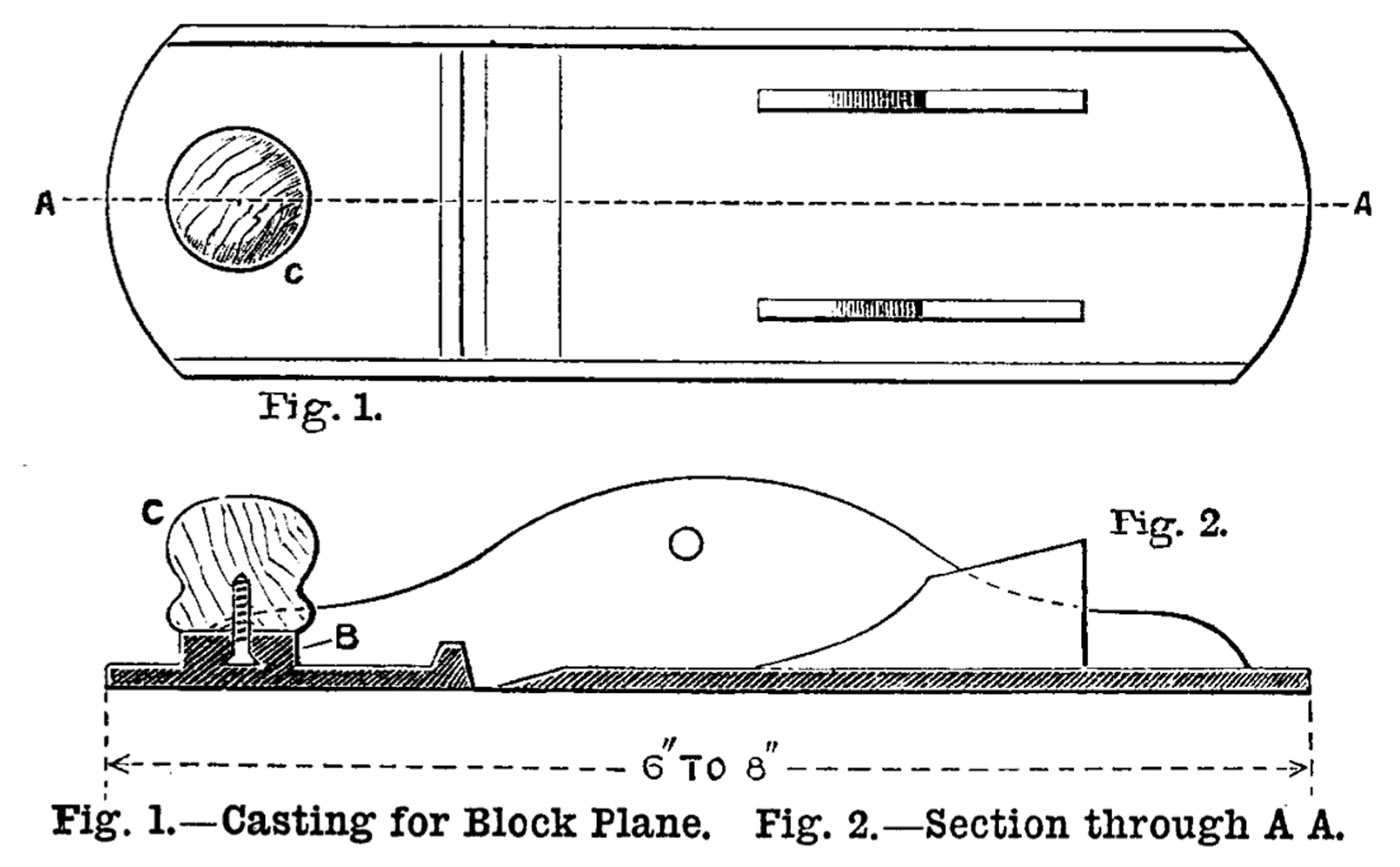
Figs. 1 and 2 represent in plan and section the shell of a block plane, which is made either in iron or in gun metal, in various sizes, and under various modifications. It is, however, only worth the trouble of making when not of very small size; use full dimensions would average from 6 inch to 8 inch in length.
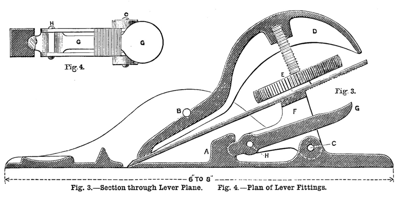
I do not show the plane complete, because the wedge and screw are precisely like those shown in Fig. 3, and the same description will apply to both. The latter, Fig. 3, shows a very neat little plane with a lever adjustment for the setting of the iron, and one that can be made without much difficulty. These are to be bought in the shops, but any one possessing a moderate degree of skill in metal working can make two or three of different dimensions for home use.
In each case construct the patterns exactly like their castings, except, that in Fig. 3, the little socketed recess in the piece A will be left to be afterwards drilled and countersunk, as also will the small holes at B and C. Lest the very thin sides should become rammed inwards or outwards by the moulder, plane up a temporary bridge of wood to just fit between the sides. This will preserve their parallelism, and when the sand is rammed sufficiently around the sides the moulder will remove it, and complete the work without risk of getting the sides away from their correct positions.
NOTE: Click on image to enlarge.
In Fig. 2 a common wood screw is cast in the metal boss, B, to receive the circular wooden boss, C, which is struck with the hammer in order to release the iron. The pattern of the arched lever, D, Fig. 3, will be cut from a bit of hard close-grained wood, also like its casting. A pattern is also made for the screw, E, whose head is milled in the lathe. If made in gun metal the screw and head may be in one piece; if formed in cast iron the screw should be cast into the head. That portion of the screw around which the milled head is cast is made angular, square, or otherwise, to prevent it from working slack with use.
The planes sold in the shops are almost always cast in iron. But the iron is of a specially soft and tough quality such as can not be always procured in ordinary foundries. In such cases it is much better to use gun metal which will not easily fracture. In such light castings the cost is very little in excess of iron because the labour counts for more than the metal. In any case I should have the lever, D, made in gun metal; even when made of good iron, these levers will often break when a slight excess of pressure is imparted in turning the screw for tightening the iron. I should also have the screw and milled head cast in one in gun metal, rather than cast the screw into the milled head, the screw being apt to work loose in its casting in the course of time.
When cast, file the faces, and drill the various holes required.
A pin is made to bridge across the casting at B in order to afford the necessary fulcrum for the lever. This is riveted in holes which are slightly countersunk.
For the lever fittings in Fig. 3, get a bit of steel bent round, and file it to the outlines in F, Fig. 3, and Fig. 4, filing out also the recess through which the lever, G, operates. Drill the holes, C, H; prepare the lever, G, Figs. 3 and 4; pivot it in place, and then pass the pin, C, through, which attaches the rocking lever, F, to the plane.
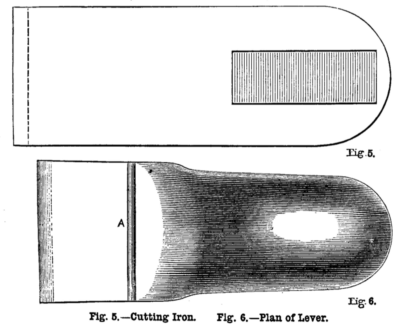
The assistance of a smith must be obtained for the cutting iron, Fig. 5, which will be ground to size and serrated while yet untempered. These serrations, as well as those on the rocking piece, will have to be done very carefully and regularly. They number about five or six to the 1/8 inch, and are sunk to about 1/32 below the level of the under face of the plane iron.
To cut these serrations, get a cold chisel of the same width, and ground slightly keener than the ordinary chisel. Lay the iron on a piece of metal, and, holding the chisel transversely at right angles with the edge of the iron, strike it a smart but dead blow. That will not only indent the metal, but will raise a burr or ridge formed by the displaced metal. This ridge will guide the chisel for the next blow, and so on in succession like file cutting. If the chisel becomes only slightly dulled, re-grind. It will be as well to practise the cutting first on a bit of wrought iron or steel before tackling the actual plane iron. A shorter but otherwise similar series of serrations will be cut upon the top of the rocking piece, Fig. 4, and care must taken that they are both at right angles, and at the proper pitch or distance, as otherwise they will not enter and mutually coincide.
The only fitting about the lever is that involved in the coincidence of the groove, Fig. 3 B, Fig. 6 A, with the pin, and that of the front edge upon the iron.
NOTE: Click on image to enlarge.
When the iron is set approximately flush with the face of the plane, the milled wheel, E, is turned, tightening the iron. Then by the simple movement of the lever, C, upwards the iron is thrust forward, increasing the thickness of shaving: by its movement downwards the iron is drawn back for removing finer shavings. Thus no hammer is ever used on
the plane.
A great deal of difference of opinion exists respecting the relative merits of wooden and of iron planes. The reason is not far to seek. Many of the planes sold are such utter rubbish that they will not stand ordinary wear and tear. A broken wedge, due to an extra turn of the screw, and a broken body due to a fall, are not unfrequent accidents. The reason is that they are too often made of the commonest cast iron: and so a tool having good inherent qualities has been consequently brought into some disrepute. But this certainly does not apply to the best iron planes, although, even in these, more care is necessary than in those of wood. An amateur also making his own planes will see to it that good metal is put into them, or will have them cast in brass. For the best indoor bench work, as cabinet making, Joinery, pattern making, etc., iron planes have their own special value.
Speaking of the writer’s own trade, he would deem it quite exceptional to find a workman destitute of at least two or three metal planes. One of the advantages of these tools consists in their weight, another in the greater rigidity of metal over wood, by virtue of which they readily remove fine shavings and operate on cross-grained timber; another is that the sole does not become worn out of truth so rapidly as wood, and lastly they are not affected by heat or moisture. For the lighter and best classes of work, therefore, and for some special purposes, these planes are of service, and I have preferred to describe the making of planes of metal rather than those of wood, because the latter, as a rule, do not offer the same difficulties to amateurs and workmen as the former.
Sometimes a compromise is made in the case of wooden smoothing planes by screwing a plate of metal to the wooden sole, but this has obviously only a limited application.
Referring once more to the manufacture of homemade tools, it is, of course, infinitely easier for the majority of men to work in wood than in metal; and it is this facility in wood working, as compared with dealing with metal, that inclines most men to work in the former rather than in the latter. This, however, should not altogether tend to induce men to discard metal for wood because the former happens to be more intractable. ![]()
The above article has been taken from the 1889 trade publication “Work” (Saturday, July 6, 1889.) The name of the foreman pattern maker is not known, but the author does present a valuable insight into the casting processes of the day, and of planemaking in general.
For Part I on Casting An Iron Trying Plane, click here.
For Part II on Casting An Iron Smoothing Plane, click here.
For Part III on Casting An Iron Chariot Plane, click here.
For an article on Casting An Iron Rebate Plane, click here.
Last Updated: