DID YOU KNOW…
The descriptive terminology used by planemaker’s and collectors can be somewhat confusing to the beginner. For example there was never any real standardization of the various parts of a plane as such, but the names tended to follow the same general pattern.
Planemaking – Casting An Iron Rebate Plane
NOTE: Click on image to enlarge.
An Iron Rebate Plane.
By A Foreman Pattern Maker.
Purpose of Rebate Plane – Why Skew-Mouthed – Effect of Skew-Mouth – Pattern for Rebate Plane – Core Box – Prints – Mouth – Filling in Blocks – Dimensions – Special Rebate Planes.
Hitherto I have treated only of those planes which are used for working over broad surfaces, the planes being traversed sideways at will to operate on any portions of these surfaces. In another and larger class of planes the action is entirely localized in the direction of the breadth, so that they remove a narrow zone of material only. These embrace the rebates, rounds, and hollows, fillisters, ploughs, beading, and other planes. They constitute by far the largest portion of the kit of a joiner and cabinet maker, and are mostly made in wood. The simplest of all is the rebate, because it operates only on flat surfaces, the irons of the other planes, the plough excepted, being mostly of various sectional forms. In few of these is the cutting action so good as in the common bench planes; first, because they have single irons only, and second, because in many cases, as for example in the moulding planes, the proper cutting action degenerates into scraping at certain sections towards the sides of the planes, where the angle which the iron makes in relation to the sole, and which should properly be normal at every portion of the curve, cannot be maintained. Moreover, all these irons are very slight in themselves, and apt to chatter on their seats.
It is to obviate somewhat the tendency of the rebate plane to chatter that it is usually made skew-mouthed. The skewing is not great, but it has the effect of causing the iron to sever the grain fibres in detail, in the same way as a chisel when directed obliquely cuts more sweetly than when it is thrust straightforward through the stuff. Making the body of the plane of metal instead of wood extra weight is obtained, and the best results possible from the rebate plane are secured.
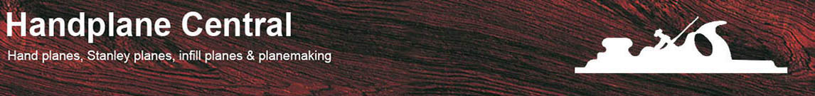
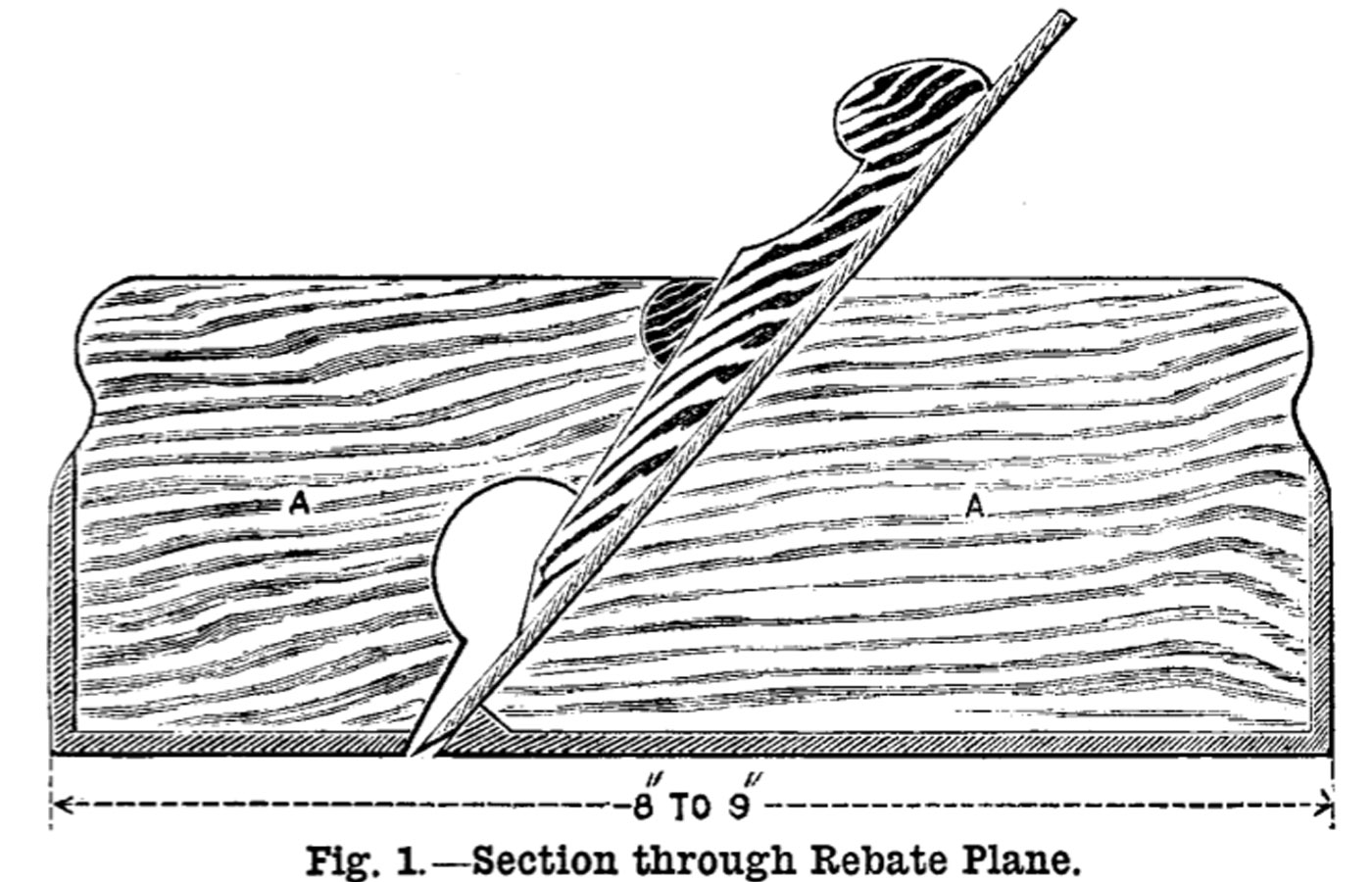
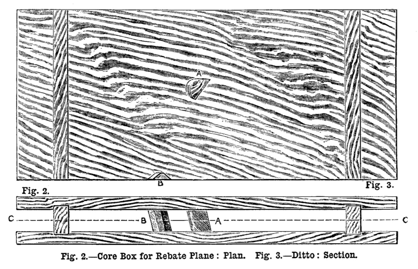
A common iron plane is shown in section in Fig. 1, the pattern in Figs. 4 and 5, and the core box in Figs.2 and 3. In Figs. 4 and 5,the print, A, of the pattern is of the same thickness as the width between the inside faces of the casting. This print is planed to gauged thickness first of all, and upon it the pieces, B, which are of the same thickness as the sides of the castings, are nailed. The thickness of these sides when finished should be 1/8 inch. In the pattern they may be 3/16 inch, or a trifle more if it is intended to plane the sides in preference to filing them.
Before being fastened on, the holes through which the shavings have to escape are cut out, and usually the top edges are shaped to an ornamental outline, somewhat as shown in the figure. Note the great breadth of the print, which is quite double that of the pattern itself, in order to enable it to balance the core properly, the pattern moulding upon its side. Being so shallow it is not necessary to make any taper in the sides of either pattern or print. If made dead square, the rapping will cause it to deliver freely. This is a case where coring out is quite necessary, because the deep and narrow body of sand between the sides would not deliver from a pattern made just like its casting, except by imparting an extravagant amount of taper thereto.
NOTE: Click on image to enlarge.
The actual mouth for the iron cannot be cut in the pattern, because it would not mould properly. This must be cut through in the casting, either with a slitting file, or with a hack saw, and finished by filing to the size required.
The core box (Fig. 2) is simply a rectangular open framed box having its ends grooved into the sides in the usual way, and having a piece, A, bridging across it to act as a stop for the wedge, and also a triangular bit, B, forming a bedding for the lower end of the iron which comes just above the bevelled facet.
The filling in blocks shown at A A (Fig. 1), made of any suitable hard wood, are fitted carefully in place, using red lead to test the accuracy, or otherwise, of their contact. Before fitting them, it will be necessary to rough file the inside faces of the casting, and to check their parallelism with internal calipers, to be sure that the width at the upper portion is not less, but of the two slightly greater than the width lower down. As in the previous examples, see that the fit is perfect everywhere, and also that the bedding of the iron on its seat, and of the wedge on its iron, are perfect, in order to diminish risk of choking and chattering. The section (Fig. 1) shows the relative arrangements of blocks, iron, and wedge so clearly that further explanatory remarks are unnecessary.
I have not given many dimensions in this instance, because the drawings are proportional, and all measurements can be scaled. An ordinary rebate plane is about 9 inch or 9-1/2 inch long. The width for an iron plane may range from 1 inch to 1-1/2 inch.
NOTE: Click on image to enlarge.
It is not advisable to exceed 1-1/2 inch, nor is it well to go below 1 inch in an iron plane; though in wood we may go to 1/2 inch and 3/8 inch.
In rebates, as in smoothing planes, it is often convenient to bring the iron close to the front, for the purpose of working right up to a shouldered end. This cannot be done in a plane made of wood, because of the weakness of the short grain. But such a plane is easily made in metal. The one here figured might be modified in such a way, but usually the tool is made altogether smaller. One of this special type will be described in a future paper.
It has been advanced that no one who can buy a tool will make one; but this is by no means the case, as many a professional workman will be found who will not only make, but even contrive special tools for special purposes. Moreover, the methods of making tools described in this and other papers on the subject are useful as forming a stepping-stone to the art of pattern making, which will eventually be treated in a more comprehensive manner. ![]()
The above article has been taken from the 1889 trade publication “Work” (Saturday, July 20, 1889.) The name of the foreman pattern maker is not known, but the author does present a valuable insight into the casting processes of the day, and of planemaking in general.
For Part I on Casting An Iron Trying Plane, click here.
For Part II on Casting An Iron Smoothing Plane, click here.
For Part III on Casting An Iron Chariot Plane, click here.
For an article on Casting An Adjustable Block Plane, click here.
Last Updated: