DID YOU KNOW…
You can now follow Handplane Central on Twitter or find us on Facebook. If you need to ask a question about a particular plane, or even just a general question, join the Handplane Forum and ask away!
Practical Plane Making (Part I)
The following article by William J. Armour was originally published in four parts in “Work, The Illustrated Journal for Mechanics” in early 1898. Armour was a plane maker from the Pimlico area of London and is noted in W.L. Goodman’s book “British Planemakers From 1700”. A number of his hand planes, saws and other woodworking tools have surfaced over the years as he was in business for some 35 years or so. At the time these articles appeared in “Work”, William Armour was located at 47 Hindon Street, Pimlico.
W.J. Armour appeared to have an association with the well known planemaking firm, John Moseley & Son, and may have worked there at some stage. Indeed some of Armours’ advertisements from “Work”, as well as various markings on his hand planes, stated “From the Original John Moseley & Son” but the exact connection is not known. One thing that is certain is that his knowledge of plane making is quite considerable and very sound. In the introduction to his articles, Amour stated his intention to cover five areas of planemaking: flat (bench) planes, moulding planes, stop work planes (ploughs, fillisters and dado grooving planes), coachmakers tools and iron planes, and planes made to drawings. The methods described in making flat planes, moulding planes and stop work planes are quite detailed. However, making planes to architects drawings, and making sash templates are decsribed briefly at the end of the section on moulding planes (Part II). Unfortunately coachmakers tools and iron planes are not covered at all, and there’s a possibility that the intended final chapter was either not written or not published. Likewise there are no later references in “Work” to the missing section and the last advertisement for W.J. Armour tools appeared in March of that year.
Practical Planemaking 1
By W. J. Armour
Of all the tools used by carpenters, cabinet makers, coach-builders, and other workers in wood, there is none that they are more familiar with than the plane; but there has always been a mystery surrounding the method of making planes. In the columns of different journals there have been from time to time articles touching this subject, but none of those that I have seen are at all correct. In many instances the file has been made to play a very prominent part; this is quite a mistake, as in making a flat plane it is not used at all, except to file the edges of the trimming. The different planes will be dealt with in the following order: Firstly, flat planes, such as jack, try, and smooth planes; secondly planes for moulding work, such as hollows and rounds, beads, ovolos, O.G.’s, and sash planes; thirdly, stop work, such as ploughs, fillisters, and grooving planes; fourthly, coachmaker’s tools and iron planes; and fifthly, planes made to drawings or patterns.
The Jack Plane
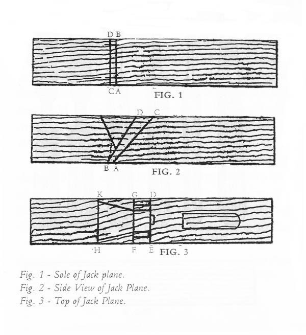 The wood selected should be cut from a centre plank of beech as near to the bark as can be, then it is put into a tank and steamed for about twenty-four hours, which drives out the sap and turns the wood from white to a reddish colour; this is done to assist the drying, and the sap being out of the wood it is not liable to cast. It should not be used before it is three years old, then it is cut into 17-in. lengths, which are planed up to 3 in. square. In all planes, that part which is closest to the bark is made the sole (see Fig.1) or working part, that being the hardest part of the wood. Measure 5 3/4 in. from the fore end and strike a line A B; this is called the bed line of the mouth. Strike another line C D about 3/16 in. from the bed line; this is called the mouth line. Then from the bed line strike the pitch of the bed (a c. Fig. 2), which is varied somewhat according to the work to be done; it is generally an angle of about 50 degrees. Then strike a line (D E, Fig.3) from the top of the bed line across the top of the plane; this is the top of the bed. From this line measure 1 in., then strike a line across (F G, Fig. 3); this is called the butment line. If the iron used is 2 1/4 in. wide, measure from the butment line 2 1/2 in. (it being in nearly all cases of bench planes 1/4 in. wider than the iron used); strike a line H K, which is called the front; then strike a line B D (Fig. 2) on the side of the plane from the butment line to the mouth line on the face of the plane.
Next draw a line from the front on the top of the plane to about 7/8 in. on the side to the line running from butment to mouth; then gauge the width of iron on the face and allow 1/16 in. wilder on top; then gauge 1/4 in. on each side of the front line of the cheek. Next take a chisel and mark with a slight blow to break the grain on the top from the front line to the butment line, and from there to the bed line; do the same on the other side. Next, with a very strong gouge and mallet, sink down to a level of the bed line and front line, suing a guide (Fig. 4) from time to time to see that you do not go too deep; then bore with a 1/8-in. nose-bit from the centre of the mouth on the sole in a line with the bed line, care being taken not to come below the level of the bed. Then take a small saw and cut to each side where gauged to size of iron; then with a thin chisel knock away the wood to the bottom of front; this is called the wear, and is shown by the dotted line in Fig. 2. Now we have an opening right through. Next take a thin saw and cut in through the cheeks for the wedge on each side; then a gentle tap with a small chisel will knock out the core. There is now room for 1 1/4-in. chisel to pare the bed; this is done by holding the chisel firmly in the right hand, bringing the shoulder on to the handle, and pressing hard on the handle, care being taken to keep the chisel quite flat. Whenever it is found that the chisel digs in, always remove the bottom portion; never commence a fresh stroke until this is done, otherwise the bed will be full of ridges. Having pared the bed, take a tool called a float and smooth the side where the wedge goes in; two varieties of float are shown in Figs. 5 and 6. Then pare the butment straight; this is done by holding a thick chisel firmly in both hands with the edge upward. Then, having got the iron in, strike a line with the marking awl for the mouth and pare the wear.
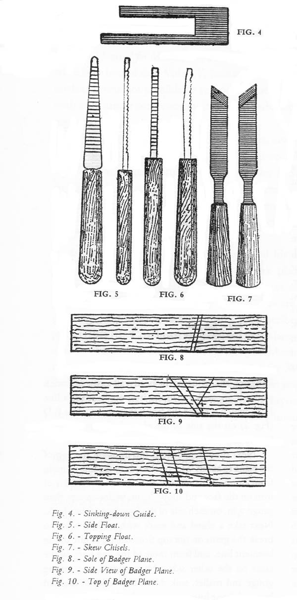 Next take some skew chisels (Fig. 7) and clean the cheeks, front, and throat, afterwards cutting the notch hole for the top iron screw. Let in the wedge, and grind and fit the irons and bed. It is important that the pressure of the wedge should be at the bottom, otherwise the iron will chatter and the top of the butment will be liable to split. Then make the wedge and shoot the ends by putting in a block of wood and plane across. Next let in the tote and trim the plane edges; and finally, glue in the tote, knock the iron and wedge in, and shoot the face, always with the irons in, otherwise the pressure on the bottom of the bed will force out the wood behind the bed, which is called backwood. If this is not done the plane will never work easily. The foregoing instructions apply to all kinds of flat planes. With the exception of badger planes, which are skew-mouthed to work in the corner of rebate, where the whole of the setting is on the skew (see Figs. 8,9, and 10). Then utmost care is required in the sinking down to prevent going too near the working corner, which, when finished, is worked down to a feather edge. It is better to plane the side away when finishing than to pare too closely. There are two other important points to be observed in making a badger: the first is to see that the irons are properly fitted. The method of fitting the top iron of a badger plane is as follows: first see that the cutting iron is true on the face, and that the back is ground true (it should be slightly hollow); then screw the top iron to the cutting iron and file the sides to the size of the cutting iron. Then, on a small grindstone, hollow the under part of the bevel of the top iron so that it fits perfectly to the face of the cutting iron. Grind the bevel of the top iron to a strong round bevel; this is done by rolling the bevel on the grindstone. The reason for this is that the edge should be sharp, but strong enough to resist the shaving. To break the shavings immediately that are cut by the cutting iron is the work that all top irons have to do, and the closer the top iron is to the bottom or cutting iron, the finer is the shaving. The top iron should be twisted a little so that the working corner touches the face of the cutting iron first, so that when the screw is screwed up, that being the weakest part, will spring down, and the whole of the edge will be close down to the face of the cutting iron. If this is not observed, the shavings will get under and the plane will choke. The second important point is the bedding; great care should be taken that too much pressure is not placed on the working corner, as it is very weak, on account of the bed coming so close to the corner; at the same time, enough pressure is required to prevent the iron from chattering.
It will be observed that the only tools used are chisels and a side float; the file is not used at all. One of the most important things is that the chisels used must on no account be sharpened on the face; if this rule is not observed, it will be impossible to pare.
Click here for Practical Plane Making (Part II)
Part I | Part II | Part III | Part IV